Controllers
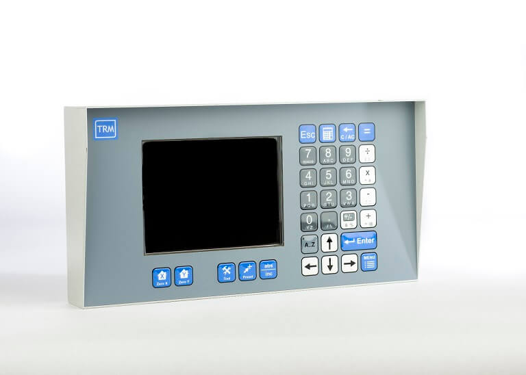
Whether its a paper guillotine, metalwork guillotine, shearline or any other form of measuring system the TRM GOTO controller is the solution for you.
Precision control has been the backbone of all of TRM's developments over the years and as such the GOTO controller, albeit competitively priced, has the same high precision control software and hardware combination of it's larger siblings.
Contact us with your requirements for a full quotation. Customisation options available.
The PMC Multi-axis Motion Controllers are high specification motion controls based on hardware and software specifically developed for the embedded motion control industry. Available in a range of sizes and enclosures, our motion controls are programmable with MAP, our software application. The PMC multi-axis motion controllers are suitable for automating a vast variety of machines i.e. glass rolling, tube forming, foil winding, XYZ profiles and many others. Should you have a machine that is, or is about to go into, production our development team will endeavour to assist in customising our motion controllers to suit your needs.
 |  |  |
Our controllers can be used not only in motion control applications, but also in temperature control, data acquisition, open loop control, applications making it an affordable and simple solution as there is no need for an additional HMI or additional PLC. For some systems that do not require a LCD and keypad, we can supply the main board in a "blind" case and multiple units can be linked together if needed.
Applications:
| Features:
| Industries:
|
Software
Our motion controllers are intended for use on machines large or small that have a simple or complex process cycles. Programming is carried out in our MAP application which allows the machine builder or operator to create programs based on sequences of commands that are all available from easily navigable drop down menus. Once a command is selected, the parameter fields are completed and the next command chosen. There are over 100 commands to choose from and all are fully documented with examples, creating a program is just like filling in a spreadsheet. Should the user wish to code their own program, that is also possible in the popular 'C' language amongst others.
Controllers are shipped with an Operating System called Blackthorn which is entirely our own design and optimised for speed and stability in our motion controllers. It is worthwhile pointing out that this is not based on DOS, Windows or Linux so is not susceptible to the security issues, constant updates and virus attacks that each of them has. Boot time from cold takes only a couple of seconds and you can be ready to run a machine well within 10 seconds!
Our multi-axis motion controllers are designed from the outset to run cool, for 24 hours a day, 7 days a week, 365 days a year and to be stable and be accurate. We appreciate that downtime is valuable and MAP has a service menu built in along with notification messages to aid planned maintenance schedules.
A 2 axis motion control example using the MAP program

In the image opposite a simple program is shown that will control two axis and move to two locations to carry out a simple operation.
- Initially on line 0 the speed of each axis is set to 50% of the maximum allowed speed
- Secondly a move command is given and each axis will move to its corresponding position, in this case X=22.5mm and Y=49.8mm
- The system then waits for an input to switch before any further commands are processed.
- Once the input is in the correct state a move command is issued to send both axis to X=1266 and Y=490
- When in position an output is immediately turned on and the next line is processed
- This then waits for an input to change to 0
- Once the condition is met the next line changes the output to an off state
- The system then waits for 10 seconds before automatically starting again
This simple program can be expanded by selecting further commands which could be calculation based, time based, control other IO, results based on data received over serial comms and many many other options.
The PMC mult-axis motion controller can control AC/DC servo and stepper type motors. Below is a video of a Stepper being run up to a high speed however invariably most applications do not require a motor to run at full speed but under load and therefore at high current.
Running a Stepper Motor up to 9000RPM
|
Specifications Overview | ||||
| Axis: |
| None Volatile Ram: |
| |
| Programming: |
| High Speed RAM: |
| |
| Jog Wheel Encoder Inputs: |
| Sample Period: |
| |
| I/O: |
| Ports: |
| |
| Encoder Inputs: |
| Microprocessor: |
| |
| Encoder Registers: |
| Processing Speed: |
| |
| Step Controllers: |
| Flash Memory: |
| |
| Motion control: |
| Options: |
| |
Case Sizes
Other case sizes are available for our motion controllers to suit a variety of machines allowing door mounting, integrating into the machine itself, pendant mounting or even remotely mounting in a pedestal are a few of the options available.
Volume users
For volume users where standard doesn't fit, we have a customising service that allows case styles to be changed, overlays to be created with custom colours and logo's, and if necessary custom keypad layouts. Even the software can be semi-customised as standard opening screens can be added by uploading a JPEG image, Operator screens can be laid out by changing a few simple parameters and for those that want a full solution we can offer a design/installation or programming service.
Typical Connections.
Click to enlarge:
 |  |
Custom Software
In the above examples the same motion controller is used however a new program is written to operate as required by the application. Keypad layouts or the screen position can be changed to suit the application.
Expansion boards
Sometimes more IO is required or specific power supplies, Analogue conditioning, relays, connectors and even the positioning of connections to make cable runs as neat as possible. We therefore provide a range of IO boards to integrate into a machine that link to the motion controller and makes wiring considerably easier. Depending on volume these can also be designed to suit the machine.
Customised Controllers
Customisation can be as simple as adding your logo or changing colours! We can revise the motion controllers overlay as needed and upon customer approval have a number produced so that the motion controller is branded and is styled the same as the machine it is mounted in. This appeals to OEM's as it is a key selling point and can give a consistent look across a range of machines.
We can also help with machine design, cable routing and specifying electrical components through to a full design/prototype process. As we have worked with many manufacturers of machines over the years we have a wealth of knowledge that you can call on to ensure your machine has the most competitive edge possible. Sometimes the cheapest way of doing things is not the best and it is the best that we will always look to provide.If you have a requirement that you need to fulfil please contact us.
|
|  |


Specifications in Detail
Controller Power Supply:
The controller is supplied from a single 24VDC source in most applications. It can run from 12V to 32V however higher voltages will be clamped as the controller has internal protection.
Command Outputs:
There are four +/-10V motion control outputs available for connections to AC or DC drives. These provide the command signals to position each axis accurately. Each axis can be setup as servo or stepper so that a mixture can be used where precision needs to be delivered at a price.
Stepper Signals:
It is also possible to control four Stepper motors instead of servo or AC motors via the Step and Direction signals provided for each axis. This type of motor whilst more cost effective has it's limitations and if precise movements are required Servo motors should be used. (also see TTL Outputs).
TTL Outputs:
If the stepper signals are not used, they can be configured as eight general purpose TTL (0-5V) outputs. Capable of driving LED's, the output power is limited but can be buffered and used to drive much greater loads.
Internal Jog Encoders:
The PMC controller has provision for up to three low resolution encoder connections. These can be used as control dials for setting speed, adjusting position manually or altering values on screen by using our MAP software functions. Depending on the controller style chosen and order requirements, all, some or none of these may be fitted.
Inputs:
Sixteen opto-isolated inputs are available for connection to switchgear, Sensors, PLC's etc. Polarity is user selectable for PNP/NPN use in banks of 4 so it is possible to use a mixture of signalling methods.
Encoder Inputs:
We provide four encoder channels for use with servo motors. The signals available for each channel are A, B, /A, /B and Z. Settings available in MAP allow for the number of pulses to be programmed and if it is a rotary or linear type.
Outputs:
There are twelve 3 amp outputs that have current limiting built in to ensure no damage can be caused. Each bank of four outputs has a status signal that is fed back to the control software to enable an alarm should an error occur.
The output voltage can be selected by the installer as the VCC pin is available for external connection. Most installations have this linked to the supply pin however it allows other supplies to be used at a different voltage if required. Typically this is 24V however up to 36V can be used as a maximum with the lowest being 6V. The controller itself should be run from 12-24V as a standard.
A clamping diode is provided on each output to prevent energy spikes from inductive loads damaging the output device. These are only 1 amp devices with a 30 amp non-repetitive peak current which are suitable for most small relays etc. Contactors and larger inductive loads should always be suppressed at source with an appropriate device to prevent any noise transmission back to the controller.
Communications:
RS232 is fitted as standard along with RS485. CAN is currently an option though we plan to move our products onto this standard as a preference. Controllers can be connected to Computers, Printers and to other controllers as required to enable data to be uploaded or downloaded.
RS485 is a multi-drop format and nodes need to be configured with a logical number. We provide for 256 address' which is usually more than enough as Custom modules can be manufactured if needed to provide for specific IO.
Memory:
The PMC controllers have the facility to expand the internal memory if required with the use of SD cards. Designed to be installed at production, controllers should be ordered with this option if required.
Keys:
Depending on the case design and software, controllers can come with many different keypad layouts. Products designed for specific basic tasks may only have a few keys for navigation and data entry.
Where files are to be stored a compact alpha numeric keypad may be used but where data entry and modification is to be used regularly every hour of each day we have different layouts of full QWERTY keypads designed for fast data entry.
Displays:
Controllers can come with many different display options depending on the size of machine, location and information to be displayed. Typically we have 5.7” and 10.4” displays as standard although custom designs have used 1” and 3.5” and other sizes are available. While monochrome used to be the standard, virtually all controllers now use colour displays. This is not only due to the low cost but also as colour messages can instruct or warn an operator more effectively.
Enclosures and Mounting:
Custom enclosures are available depending on quantity and can be designed in conjunction with the customer to fit the machine. Standard enclosures are available and are suitable for many machines without modification.
Panel, POD and Boom Arm are all different types of mounting that are available to suit a wide variety of machines, if you don't see an option suitable please contact us with the required details.
Connections:
Most controllers are fitted with three D type connectors. A 37 way for Power, Digital Inputs and Power Outputs. A 44 way for Stepper signals, command signals, encoders and Analogue. And a 15 way for Serial communications.
A USB type A connection is also provided for Pen drive use.
Analogue Inputs:
Four inputs are provided with a +10/-10V range that can be easily converted externally to different ranges e.g. 4-20ma or 0-2V. Internal capacitors are fitted at 47pf however these can be modified by special order to suit the application.
A typical application for the inputs is monitoring load cells. Values can be read in to the controller and either averaged or the Max and Min found to enable calculations to be performed and outputs be controlled as needed.
PLC Inputs:
Four extra PNP Inputs IP16:19 are provided where outputs OP16:19 are not used. If, however, the outputs are used the inputs can then be used to monitor the output state to determine if the output is actually on or has failed.
Amplifier Enable:
The transistor output of an opto-coupler is provided for connection to a drive enable circuit. When motion commands are used and the system is told to run, the Drive enable signal is activated to allow movement of the axis.
Real Time Clock:
Although in most applications the use of time and date is not required, there are some where data needs to be recorded or maintenance schedules met. A battery backed RTC is provided for this requirement. Laser trimmed, these devices are highly accurate and facilities are provided to allow the system manager to change the date and time according to their time zone and time of year.
Protective Window:
All our controllers use a 6mm hard coated window to resist scratches and provide strength to prevent damage to the LCD display that would otherwise be easily damaged. This is bonded in place to also provide a seal to prevent dirt and liquids entering the controller.
Overlay:
A polyester overlay is bonded to an Aluminium front plate of between 2mm and 3mm thick depending on the controller. This gives great strength and noise immunity whilst being readily changed to suit customers needs. An over can be customised with a company Logo, company colours or a complete re-design changing the key lettering too.
Software:
As our controllers run from TRM's own operating system, the customer can choose to create their own Bespoke software which will run on the controllers to allow control of a process or machine to suit the customers requirements. If something more "off the shelf" is required our powerful programming language MAP may be used:
MAP:
This is a programming language that we have developed over many years that is now extremely powerful and flexible; there are not many machines that cannot be controlled.
All IO can be handled using this software along with completing basic and complex calculations. Values can be stored in any of the 256 registers that alone can be configured as Integer, Floating Point (values with a remainder or fraction), Signed Integer (32 bit), Unsigned Integer (32 bit).
Position of each axis can be controlled and set from direct values, calculated values, operator entered values or from values entered using the Jog dial input.
PMC Controller Connector – 37 way D Male. | ||
|---|---|---|
Pin | Signal | Description |
| 1 | GND | Controller Supply |
| 2 | +24V DC | Controller Supply |
| 3 | VDDIO | Normally +24VDC |
| 4 | VDDIO | Normally +24VDC |
| 5 | VDDIO | Normally +24VDC |
| 6 | VDDIO | Normally +24VDC |
| 7 | VDDIO | Normally +24VDC |
| 8 | DRV 8 | DRIVER OUTPUT |
| 9 | DRV 9 | DRIVER OUTPUT |
| 10 | DRV 10 | DRIVER OUTPUT |
| 11 | DRV 11 | DRIVER OUTPUT |
| 12 | DRV 12 | DRIVER OUTPUT |
| 13 | DRV 13 | DRIVER OUTPUT |
| 14 | DRV 14 | DRIVER OUTPUT |
| 15 | DRV 15 | DRIVER OUTPUT |
| 16 | DRV 16 | DRIVER OUTPUT |
| 17 | DRV 17 | DRIVER OUTPUT |
| 18 | DRV 18 | DRIVER OUTPUT |
| 19 | DRV 19 | DRIVER OUTPUT |
| 20 | GND | Linked to Pin 1 |
| 21 | +24V DC | Linked to Pin 2 |
| 22 | INP 0 | Opto Isolated Digital Input |
| 23 | INP 1 | Opto Isolated Digital Input |
| 24 | INP 2 | Opto Isolated Digital Input |
| 25 | INP 3 | Opto Isolated Digital Input |
| 26 | INP 4 | Opto Isolated Digital Input |
| 27 | INP 5 | Opto Isolated Digital Input |
| 28 | INP 6 | Opto Isolated Digital Input |
| 29 | INP 7 | Opto Isolated Digital Input |
| 30 | INP 8 | Opto Isolated Digital Input |
| 31 | INP 9 | Opto Isolated Digital Input |
| 32 | INP 10 | Opto Isolated Digital Input |
| 33 | INP 11 | Opto Isolated Digital Input |
| 34 | INP 12 | Opto Isolated Digital Input |
| 35 | INP 13 | Opto Isolated Digital Input |
| 36 | INP 14 | Opto Isolated Digital Input |
| 37 | INP 15 | Opto Isolated Digital Input |
PMC Controller Connector – 44 way D Female. | ||
|---|---|---|
Pin | Signal | Description |
| 1 | A0 | Encoder Channel |
| 2 | B0 | Encoder Channel |
| 3 | Z0 | Encoder Channel |
| 4 | A1 | Encoder Channel |
| 5 | B1 | Encoder Channel |
| 6 | Z1 | Encoder Channel |
| 7 | A2 | Encoder Channel |
| 8 | B2 | Encoder Channel |
| 9 | Z2 | Encoder Channel |
| 10 | A3 | Encoder Channel |
| 11 | B3 | Encoder Channel |
| 12 | Z3 | Encoder Channel |
| 13 | Step0 / TTL1 | Stepper / TTL Driver |
| 14 | Step2 / TTL5 | Stepper / TTL Driver |
| 15 | GND | Ground |
| 16 | +5VE | Encoder Supply |
| 17 | A0\ | Encoder Channel |
| 18 | B0\ | Encoder Channel |
| 19 | AGND | Analogue Ground |
| 20 | A1\ | Encoder Channel |
| 21 | B1\ | Encoder Channel |
| 22 | +5VE | Encoder Supply |
| 23 | A2\ | Encoder Channel |
| 24 | B2\ | Encoder Channel |
| 25 | AGND | Analogue Ground |
| 26 | A3\ | Encoder Channel |
| 27 | B3\ | Encoder Channel |
| 28 | AGND | Analogue Ground |
| 29 | Step1 / TTL3 | Stepper / TTL Driver |
| 30 | Step3 /TTL7 | Stepper / TTL Driver |
| 31 | MC0 | Motion Control Output |
| 32 | MC1 | Motion Control Output |
| 33 | MC2 | Motion Control Output |
| 34 | MC3 | Motion Control Output |
| 35 | ADC0 | Analogue Input |
| 36 | ADC1 | Analogue Input |
| 37 | ADC2 | Analogue Input |
| 38 | ADC3 | Analogue Input |
| 39 | DIR0 / TTL0 | Stepper Direction / TTL Driver |
| 40 | DIR1 / TTL2 | Stepper Direction / TTL Driver |
| 41 | DIR2 / TTL4 | Stepper Direction / TTL Driver |
| 42 | DIR3 / TTL6 | Stepper Direction / TTL Driver |
| 43 | ENA C | Opto Isolated Collector |
| 44 | ENA E | Opto Isolator Emitter |
PMC Controller Connector – HD 15 way D Female. | ||
|---|---|---|
Pin | Signal | Description |
| 1 | RX | RS232 |
| 2 | TX | RS232 |
| 3 | RTS | RS232 |
| 4 | CTS | RS232 |
| 5 | GND | |
| 6 | A | RS485 |
| 7 | B | RS485 |
| 8 | Y | RS485 |
| 9 | Z | RS485 |
| 10 | GND | |
| 11 | CAN H | CAN BUS |
| 12 | CAN L | CAN BUS |
| 13 | N/C | |
| 14 | N/C | |
| 15 | GND | |
 Pick & Place, Conveyor Control, Tank Contents, Labelling and Bottling are some of the industries we are involved in.
As our controllers are completely flexible and programmable we have the ability to automate most machines. With full PLC capabilities and completely programmable, conveyor, product sorting, weighing, mixing and analysing are just some of the processes the SMC can be used for. This system is also available via our partner company PCI Instruments. PCI have a wealth of knowledge in the instrumentation business area and can advise the best way to imlement the system with matching sensors.
Using weighing as an example the process could be as follows:
- The controller prompts the user to enter a number of quantities for a "recipe"
- Valve A is turned on by Output 1 of the controller.
- The controller could then calculate how much water had passed by using a flowmeter attached to an input and once the desired quantity is reached turn off the output.
- A mix of other liquid and powder ingredients could then be measured out in a similar way by, flow, volume, weight etc. and pumped, blown, tipped, or conveyed into the mixing tank.
- Once all ingredients have been processed a weigh check on the tank may be done to enable the process to continue or to alarm, alerting the operator to missing ingredients caused by burst pipes or blockages.
- Mixing of the ingredients can now be started where times, speeds and variations can all be programmed. For example, an initial slow mix may be initiated for 5 minutes followed by a gradual increase in speed until all the ingredients are thoroughly mixed.
- The mixing cycle is then stopped and a dispensing cycle started which may be the filling of containers on a conveyor with a sensor input to tell the controller when the container is in position.
- A valve is then opened for a period of time or a pre-programmed weight is achieved.
- The valve would then be turned off and the conveyor indexed.
This is a basic example of a process and there can be many variations to this, one of which could be that the mixture is heated and cooled which would add further IO requirements to the controller program all of which can be controlled via MAP. Many of the stages of a process could be broken down into separate MAP programs and stored in files so that they can be called by the main program as needed. This also make new program creation much easier as many sub programs may have been written already saving time in setting up and testing.
Another simple application may be for rejection of parts. On a conveyor line with many items passing per minute each item could be scanned or weighed and if not in specification an output would turn on the eject the part from the line. Counters can be setup to record how many have been rejected based on total, time, average per hour or day; or any other configuration the operator wishes to see.
As the controller is so versatile it can be supplied with just our propriety operating system called Blackthorn, the user is then free to write their own bespoke program to suit their application. This would be written so that all the IO was configured as needed and with menu interfaces to suit the parameters to be entered for a particular process. Images can also be used and swapped to illustrate a machines workings making it simpler to operate.
Please also see our case studies section for examples of machines using this controller.
Available to buy now in our online shop:![]()
An example using the MAP program on the SMC
In the image below a simple program is shown that will control two axis and move to two locations to carry out a basic repetitive operation.
- Initially on line 0 the speed of each axis is set to 50% of the maximum allowed speed
- Secondly a move command is given and each axis will move to its corresponding position, in this case X=22.5mm and Y=49.8mm
- The system then waits for an input to switch before any further commands are processed.
- Once the input is in the correct state a move command is issued to send both axis to X=1266 and Y=490
- When in position an output is immediately turned on and the next line is processed
- This then waits for an input to change to 0
- Once the condition is met the next line changes the output to an off state
- The system then waits for 10 seconds before automatically starting again
This simple program can be expanded by selecting further commands which could be calculation based, time based, control other IO, results based on data received over serial comms and many many other options.
Specifications Overview | ||||
| Axis: |
| None Volatile Ram: |
| |
| Programming: |
| High Speed RAM: |
| |
| Jog Wheel Encoder Inputs: |
| Sample Period: |
| |
| I/O: |
| Ports: |
| |
| Encoder Inputs: |
| Microprocessor: |
| |
| Encoder Registers: |
| Processing Speed: |
| |
| Step Controllers: |
| Flash Memory: |
| |
| Motion control: |
| Options: |
| |
Specifications in Detail
Controller Power Supply:
The controller is supplied from a single 24VDC source in most applications. It can run from 12V to 32V however higher voltages will be clamped as the controller has internal protection.
Command Outputs:
There are two +/-10V motion control outputs available for connections to AC or DC drives. These provide the command signals to position each axis accurately. Each axis can be setup as servo or stepper so that a mixture can be used where precision needs to be delivered at a price.
Stepper Signals:
It is also possible to control three Stepper motors instead of servo or AC motors via the Step and Direction signals provided for each axis. This type of motor whilst more cost effective has it's limitations and if precise movements are required Servo motors should be used. (also see TTL Outputs).
TTL Outputs:
If the stepper signals are not used, they can be configured as eight general purpose TTL (0-5V) outputs. Capable of driving LED's, the output power is limited but can be buffered and used to drive much greater loads.
Internal Jog Encoders:
The SMC controller has provision for up to two low resolution encoder connections. These can be used as control dials for setting speed, adjusting position manually or altering values on screen by using our MAP software functions. Depending on the controller style chosen and order requirements, all, some or none of these may be fitted.
Inputs:
Sixteen opto-isolated inputs are available for connection to switchgear, Sensors, PLC's etc. Polarity is user selectable for PNP/NPN use in banks of 4 so it is possible to use a mixture of signalling methods.
Encoder Inputs:
We provide two encoder channels for use with servo motors. The signals available for each channel are A, B, /A, /B and Z. Settings available in MAP allow for the number of pulses to be programmed and if it is a rotary or linear type.
Outputs:
There are eight outputs that have current limiting built in to ensure no damage can be caused. Four outputs are rated at 6 amps (2 pins) and four at 3 amps. Each bank of four outputs has a status signal that is fed back to the control software to enable an alarm should an error occur.
The output voltage can be selected by the installer as the VCC pin is available for external connection. Most installations have this linked to the supply pin however it allows other supplies to be used at a different voltage if required. Typically this is 24V however up to 36V can be used as a maximum with the lowest being 6V. The controller itself should be run from 12-24V as a standard.
A clamping diode is provided on each output to prevent energy spikes from inductive loads damaging the output device. These are only 1 amp devices with a 30 amp non-repetitive peak current which are suitable for most small relays etc. Contactors and larger inductive loads should always be suppressed at source with an appropriate device to prevent any noise transmission back to the controller.
Communications:
RS232 is fitted as standard along with RS485. CAN is currently an option though we plan to move our products onto this standard as a preference. Controllers can be connected to Computers, Printers and to other controllers as required to enable data to be uploaded or downloaded.
RS485 is a multidrop format and nodes need to be configured with a logical number. We provide for 256 address' which is usually more than enough as Custom modules can be manufactured if needed to provide for specific IO.
Memory:
The PMC controllers have the facility to expand the internal memory if required with the use of SD cards. Designed to be installed at production, controllers should be ordered with this option if required.
Keys:
Depending on the case design and software, controllers can come with many different keypad layouts. Products designed for specific basic tasks may only have a few keys for navigation and data entry.
Where files are to be stored a compact alpha numeric keypad may be used but where data entry and modification is to be used regularly every hour of each day we have different layouts of full QWERTY keypads designed for fast data entry.
Displays:
Controllers can come with many different display options depending on the size of machine, location and information to be displayed. Typically we have 5.7” and 10.4” displays as standard although custom designs have used 1” and 3.5” and other sizes are available. While monochrome used to be the standard, virtually all controllers now use colour displays. This is not only due to the low cost but also as colour messages can instruct or warn an operator more effectively.
Enclosures and Mounting:
Custom enclosures are available depending on quantity and can be designed in conjunction with the customer to fit the machine. Standard enclosures are available and are suitable for many machines without modification.
Panel, POD and Boom Arm are all different types of mounting that are available to suit a wide variety of machines, if you don't see an option suitable please contact us with the required details.
Connections:
Most controllers are fitted with three D type connectors. A 37 way for Power, Digital Inputs and Power Outputs. A 44 way for Stepper signals, command signals, encoders and Analogue. And a 15 way for Serial communications.
A USB type A connection is also provided for Pen drive use.
Analogue Inputs:
Eight inputs are provided with a +10 range that can be easily converted externally to different ranges e.g. 4-20ma or 0-2V. Internal capacitors are fitted at 47pf however these can be modified by special order to suit the application.
A typical application for the inputs is monitoring load cells. Values can be read in to the controller and either averaged or the Max and Min found to enable calculations to be performed and outputs be controlled as needed.
Amplifier Enable:
The transistor output of an opto-coupler is provided for connection to a drive enable circuit. When motion commands are used and the system is told to run, the Drive enable signal is activated to allow movement of the axis.
Real Time Clock:
Although in most applications the use of time and date is not required, there are some where data needs to be recorded or maintenance schedules met. A battery backed RTC is provided for this requirement. Laser trimmed, these devices are highly accurate and facilities are provided to allow the system manager to change the date and time according to their time zone and time of year.
Protective Window:
All our controllers use a 6mm hard coated window to resist scratches and provide strength to prevent damage to the LCD display that would otherwise be easily damaged. This is bonded in place to also provide a seal to prevent dirt and liquids entering the controller.
Overlay:
A polyester overlay is bonded to an Aluminium front plate of between 2mm and 3mm thick depending on the controller. This gives great strength and noise immunity whilst being readily changed to suit customers needs. An over can be customised with a company Logo, company colours or a complete re-design changing the key lettering too.
Software:
As our controllers run from TRM's own operating system, the customer can choose to create their own Bespoke software which will run on the controllers to allow control of a process or machine to suit the customers requirements. If something more "off the shelf" is required our powerful programming language MAP may be used:
MAP:
This is a programming language that we have developed over many years that is now extremely powerful and flexible; there are not many machines that cannot be controlled.
All IO can be handled using this software along with completing basic and complex calculations. Values can be stored in any of the 256 registers that alone can be configured as Integer, Floating Point (values with a remainder or fraction), Signed Integer (32 bit), Unsigned Integer (32 bit).
Position of each axis can be controlled and set from direct values, calculated values, operator entered values or from values entered using the Jog dial input.
SMC Controller Connector – 37 way D Male. | ||
|---|---|---|
Pin | Signal | Description |
| eot | ||
| 1 | GND | Controller Supply |
| 2 | +24V DC | Controller Supply |
| 3 | VDDIO | Normally +24VDC |
| 4 | VDDIO | Normally +24VDC |
| 5 | VDDIO | Normally +24VDC |
| 6 | VDDIO | Normally +24VDC |
| 7 | VDDIO | Normally +24VDC |
| 8 | DRV 8 | DRIVER OUTPUT |
| 9 | DRV 8 | DRIVER OUTPUT |
| 10 | DRV 9 | DRIVER OUTPUT |
| 11 | DRV 9 | DRIVER OUTPUT |
| 12 | DRV 10 | DRIVER OUTPUT |
| 13 | DRV 10 | DRIVER OUTPUT |
| 14 | DRV 11 | DRIVER OUTPUT |
| 15 | DRV 11 | DRIVER OUTPUT |
| 16 | DRV 12 | DRIVER OUTPUT |
| 17 | DRV 13 | DRIVER OUTPUT |
| 18 | DRV 14 | DRIVER OUTPUT |
| 19 | DRV 15 | DRIVER OUTPUT |
| 20 | GND | Linked to Pin 1 |
| 21 | +24V DC | Linked to Pin 2 |
| 22 | INP 0 | Opto Isolated Digital Input |
| 23 | INP 1 | Opto Isolated Digital Input |
| 24 | INP 2 | Opto Isolated Digital Input |
| 25 | INP 3 | Opto Isolated Digital Input |
| 26 | INP 4 | Opto Isolated Digital Input |
| 27 | INP 5 | Opto Isolated Digital Input |
| 28 | INP 6 | Opto Isolated Digital Input |
| 29 | INP 7 | Opto Isolated Digital Input |
| 30 | INP 8 | Opto Isolated Digital Input |
| 31 | INP 9 | Opto Isolated Digital Input |
| 32 | INP 10 | Opto Isolated Digital Input |
| 33 | INP 11 | Opto Isolated Digital Input |
| 34 | INP 12 | Opto Isolated Digital Input |
| 35 | INP 13 | Opto Isolated Digital Input |
| 36 | INP 14 | Opto Isolated Digital Input |
| 37 | INP 15 | Opto Isolated Digital Input |
SMC Controller Connector – HD 44 way D Female. | ||
|---|---|---|
Pin | Signal | Description |
| eot | ||
| 1 | A0 | Encoder Channel 0 |
| 2 | B0 | Encoder Channel 0 |
| 3 | Z0 | Encoder Channel 0 |
| 4 | A1 | Encoder Channel 1 |
| 5 | B1 | Encoder Channel 1 |
| 6 | Z1 | Encoder Channel 1 |
| 7 | DR0 | TTL Driver Output |
| 8 | DR2 | TTL Driver Output |
| 9 | DR4 | TTL Driver Output |
| 10 | DR6 | TTL Driver Output |
| 11 | AGND | |
| 12 | AGND | |
| 13 | CANH | CAN BUS |
| 14 | CANL | CAN BUS |
| 15 | GND | |
| 16 | +5VE | Encoder Supply |
| 17 | A0\ | Encoder Channel 0 |
| 18 | B0\ | Encoder Channel 0 |
| 19 | AGND | |
| 20 | A1\ | Encoder Channel 1 |
| 21 | B1\ | Encoder Channel 1 |
| 22 | +5VE | Encoder Supply |
| 23 | DR1 | TTL Driver Output |
| 24 | DR3 | TTL Driver Output |
| 25 | DR5 | TTL Driver Output |
| 26 | DR7 | TTL Driver Output |
| 27 | AGND | |
| 28 | AGND | |
| 29 | GND | |
| 30 | GND | |
| 31 | MC0 | Motion Control Output |
| 32 | MC1 | Motion Control Output |
| 33 | ADC0 | Analogue Input |
| 34 | ADC1 | Analogue Input |
| 35 | ADC2 | Analogue Input |
| 36 | ADC3 | Analogue Input |
| 37 | ADC4 | Analogue Input |
| 38 | ADC5 | Analogue Input |
| 39 | ADC6 | Analogue Input |
| 40 | ADC7 | Analogue Input |
| 41 | AGND | |
| 42 | AGND | |
| 43 | ENA C | Opto Isolated Collector |
| 44 | ENA E | Opto Isolator Emitter |
SMC Controller Connector – HD 15 way D Female. | ||
|---|---|---|
Pin | Signal | Description |
| 1 | RX | RS232 |
| 2 | TX | RS232 |
| 3 | RTS | RS232 |
| 4 | CTS | RS232 |
| 5 | GND | |
| 6 | A | RS485 |
| 7 | B | RS485 |
| 8 | Y | RS485 |
| 9 | Z | RS485 |
| 10 | GND | |
| 11 | CAN H | CAN BUS |
| 12 | CAN L | CAN BUS |
| 13 | N/C | |
| 14 | N/C | |
| 15 | GND | |
Contact
TRM International Ltd.
86 Moss Road
Southport, PR8 4JQ, UK.
Tel: +44 (0) 1704 563777